Understanding Thermal Bridging: The Hidden Enemy of EWI Performance
Thermal bridges let heat escape through gaps and junctions in an EWI system. Learn how they form, how psi values measure them, and how proper detailing designs them out.
External wall insulation is often described as wrapping a house in a warm coat — a fair image, right up until you notice the gaps in the coat. Thermal bridges are those gaps: localised routes through which heat escapes far faster than through the insulated wall around them. Well detailed, they are small and carefully managed; poorly detailed, they can quietly undermine much of the performance you paid for and even create damp problems the house never had before.
What Is Thermal Bridging?
A thermal bridge is any part of the building envelope where heat passes through more readily than through the surrounding construction. Heat follows the path of least resistance, and wherever an insulation layer is interrupted by a more conductive material — or simply stops — heat funnels through the weak point instead.
Bridges arise in two main ways: a break in insulation continuity, such as boards stopping short at a junction or an uninsulated reveal beside a window; or a conductive element passing through the insulation, such as steel, concrete or dense masonry carrying heat straight across the thermal layer. Metal is the worst offender, which is why steel-framed and other non-traditional homes suffer disproportionately — the frame itself acts as a network of bridges, dragging internal surface temperatures down.
The consequences are twofold: extra heat loss you pay for in fuel bills, and cold internal surfaces that attract condensation. The second is often the one occupants notice first.
Repeating, Non-Repeating and Geometric Bridges
Building physics splits thermal bridges into three families, and the distinction shapes how each is handled.
Repeating bridges occur at regular intervals across a construction — timber studs in a frame wall, wall ties in a cavity, or the mechanical fixings that pin EWI boards to the substrate. Because they recur predictably, their effect is averaged into the U-value of the whole element rather than counted separately.
Non-repeating bridges are one-off interruptions at particular locations — the wall-to-ground-floor junction, the head of a window opening, a steel lintel, a party wall junction — each assessed individually because it has its own geometry and materials.
Geometric bridges are caused by shape rather than material. At an external corner, the outside surface area is larger than the inside surface it serves, so heat has more area to escape through; corners, parapets and complex rooflines all lose heat faster than flat wall even when insulation is perfectly continuous.
A retrofit EWI project has to contend with all three — and the non-repeating junctions are where installer skill matters most.
Where Bridges Hide in an EWI Installation
EWI is exceptionally good at eliminating bridging across the main wall area, because it wraps the outside of the structure in one continuous layer. The risk concentrates at the edges — everywhere the insulation has to stop, turn or be penetrated.
Window and door reveals are the classic weak point. The main wall may carry a thick layer of insulation, yet the narrow strip of masonry between frame and face of wall is often left bare — and becomes the coldest surface in the room. Good practice is to return a slim, high-performance insulation board into the reveal so the thermal envelope connects to the window frame itself.
The starter track at the base of the system is another. The insulation has to begin somewhere above the damp-proof course, and the horizontal track that supports the first row of boards — plus the uninsulated plinth below it — forms a linear bridge running the full perimeter of the house. Insulated base rails and perimeter plinth insulation reduce the penalty.
Mechanical fixings pass through the boards to anchor the system. Each steel pin is a tiny repeating bridge; multiplied across a whole elevation they add up. Thermally broken fixings, with plastic sleeves or recessed heads capped by insulation plugs, keep the loss to a minimum.
At the roofline, the insulation must meet the eaves and verge cleanly. If the boards stop short of the soffit, a cold band runs along the top of every upstairs wall — a common location for mould in badly finished installations.
Balconies, canopies and other projecting concrete or steel elements are the hardest of all: they pass straight through the insulation line and act as fins radiating heat outwards. On a retrofit they usually cannot be removed, so the practical approach is to insulate around and beneath them as far as possible and accept a documented residual bridge.
Measuring the Impact: Psi Values and the Y-Value
Repeating bridges are absorbed into a wall's U-value. Non-repeating junctions are measured separately using the psi value — the linear thermal transmittance, expressed in watts per metre kelvin (W/mK). It describes the extra heat flow per metre length of a junction, over and above what the adjoining plain elements already account for. The lower the psi value, the better the detail.
Multiply each junction's psi value by its length, sum across the whole dwelling, and you can express the total bridging penalty as a y-value — a single figure used in SAP energy assessments. Where junction details have not been individually calculated, assessors must fall back on a default y-value, which assumes poor detailing and penalises the result accordingly [VERIFY: current SAP default y-value figure before quoting a number]. This is why properly designed and evidenced junction details are worth real points on an EPC, not just theoretical comfort.
EWI Pro, whose systems APEX installs, assesses thermal bridging alongside ventilation, airtightness and moisture behaviour when specifying a system [VERIFY: EWI Pro's psi value tables were listed as forthcoming at the time of writing — check availability].
Seeing the Invisible: Thermography
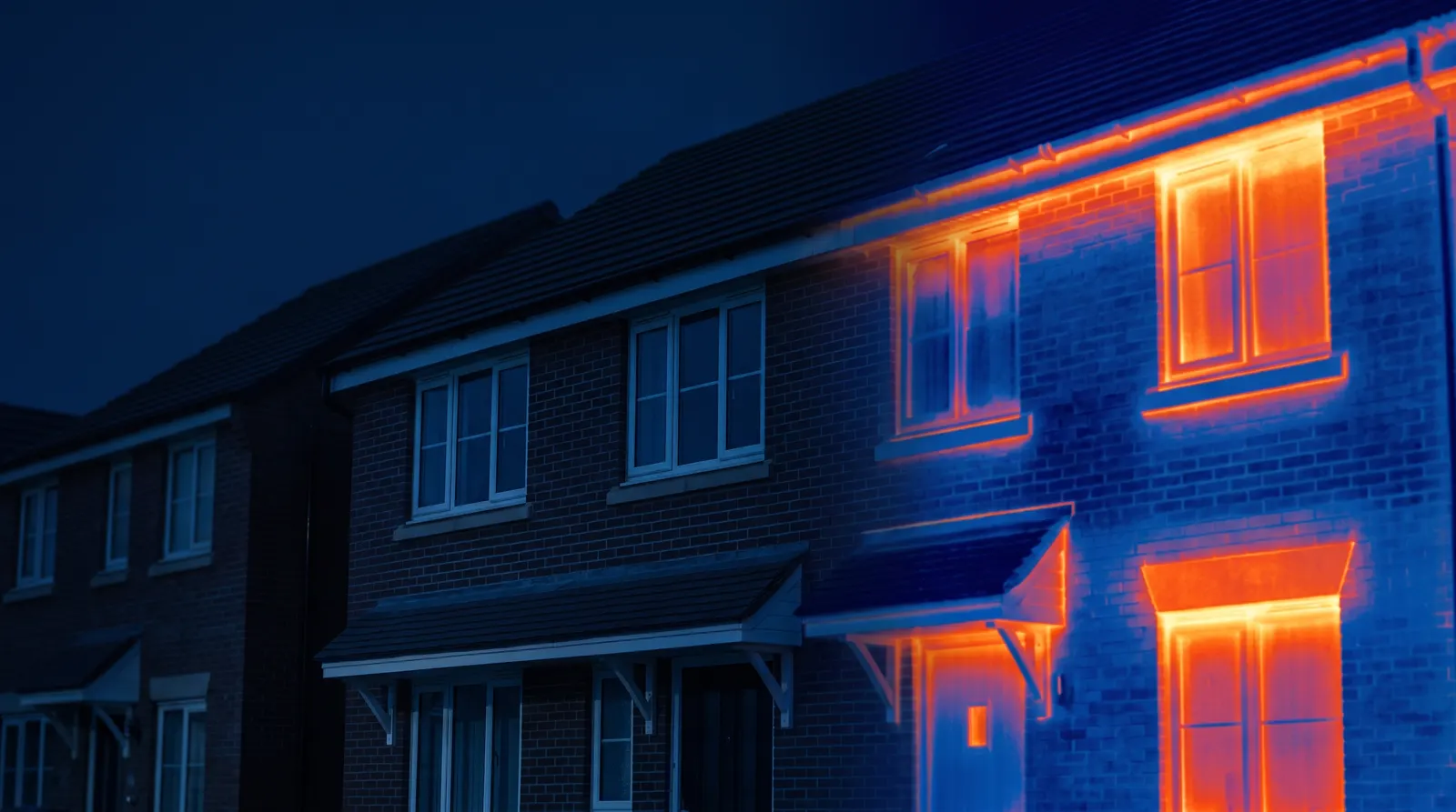
Thermal bridges are invisible to the eye but obvious to an infrared camera. A thermographic survey, carried out on a cold day with the heating running, shows bridges as warm stripes on the outside of the building; internally, the same locations show up as cold patches.
Thermography is useful at both ends of a project: before installation, to map weak points and inform the design; and after completion, to verify that boards are tightly butted, reveals are returned and nothing has been missed. Faint, evenly spaced dots at fixing positions are normal; broad warm bands at junctions are not.
Why Cold Spots Turn Into Damp Spots
Every thermal bridge lowers the internal surface temperature at that point, and when warm indoor air meets a surface below its dew point, moisture condenses out of it. Persistent condensation feeds mould, which favours exactly the places bridges create — ceiling corners, window reveals, the base of external walls.
There is a subtle retrofit risk here. Insulating most of a wall leaves the remaining bridges as the coldest surfaces in a now-warmer home, so moisture-laden air concentrates its condensation on them. An EWI system that ignores reveals or the roofline junction can therefore create damp patches where none existed. The remedy is not less insulation but complete detailing — plus ventilation adequate to manage indoor humidity.
Detailing That Designs Bridges Out
The principles of good bridge control are consistent across every project. Keep the insulation layer continuous around the whole envelope. Where a junction is unavoidable, introduce a thermal break — a low-conductivity material interposed in the heat path. Use thermally broken or sleeved fixings rather than plain steel pins. Return insulation into reveals and up to frames. Close the system properly at the base track, the eaves and every penetration. And plan all of this before the first board goes on the wall — bridging control designed in at survey stage costs little, whereas bridges discovered after rendering are expensive to correct.
This is also the heart of the fabric-first philosophy: insulation, airtightness and thermal bridging treated as one system rather than three separate boxes to tick.
Regulations and Why Documentation Matters
UK building regulations treat thermal bridging as part of the fabric energy calculation, not an optional extra. Approved Document L expects junctions to be detailed to limit bridging and condensation risk, and SAP assessments reward evidenced junction details over assumed defaults [VERIFY: cite specific Approved Document L clause if referencing formally]. For rendered EWI systems, manufacturer-approved details — such as those specified by EWI Pro — give installers and assessors a documented basis for each junction, supporting both compliance and long-term durability.
Getting the Details Right From Day One
Thermal bridging is not a reason to hesitate over external wall insulation — quite the opposite. EWI remains one of the few measures that can wrap a solid-walled or non-traditional home in genuinely continuous insulation. But the difference between a system that performs as designed and one that disappoints lives in the junctions: reveals, base tracks, fixings, rooflines and penetrations — details decided at survey stage, by people who know where the bridges hide. If you are considering EWI for your home, book a free survey and quote with APEX and we will show you exactly how every junction on your property will be handled.
// RELATED
More Articles
Condensation and Interstitial Moisture in EWI Systems
Condensation is the most misunderstood damp problem in UK homes. Learn how dew point physics, breathable EWI systems and proper ventilation keep insulated walls dry inside and out.
Render Cracking: Common Causes and Professional Solutions
Why rendered walls crack — from mix errors and missing mesh to substrate movement — how to read the crack pattern, and how professionals repair and prevent it.
Is My Wall Suitable for External Wall Insulation? A Substrate Guide
A house-type-by-house-type guide to EWI substrate suitability — solid brick, stone, cavity walls, system-built homes and rendered walls — plus the condition checks and honest fixes needed first.
// EXPERT GUIDANCE
Need Professional Advice?
Our technical team is here to help with your EWI or rendering project. Get professional guidance tailored to your specific requirements.